| 137mHz APT QUADRIFILAR ANTENNA | |
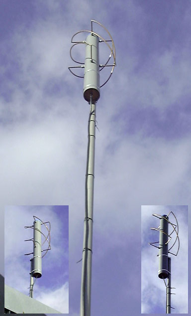 Assembled 137mHz quadrifilar 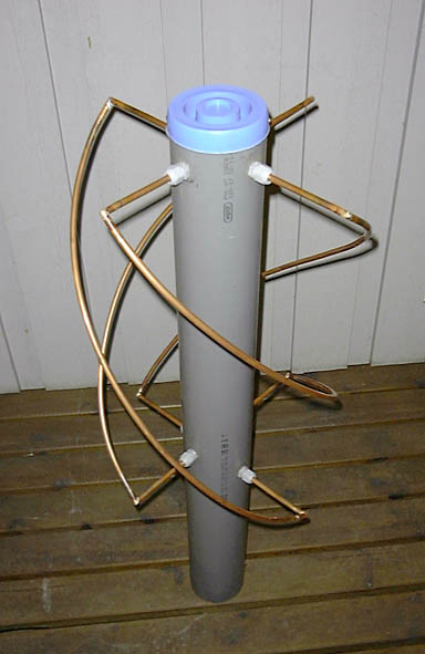 Assembled 137mHz quadrifilar 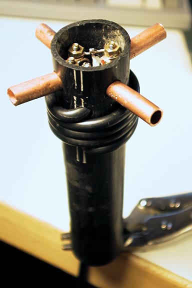 Model of balun and feed connection (Self-starting screws were used on production unit.) 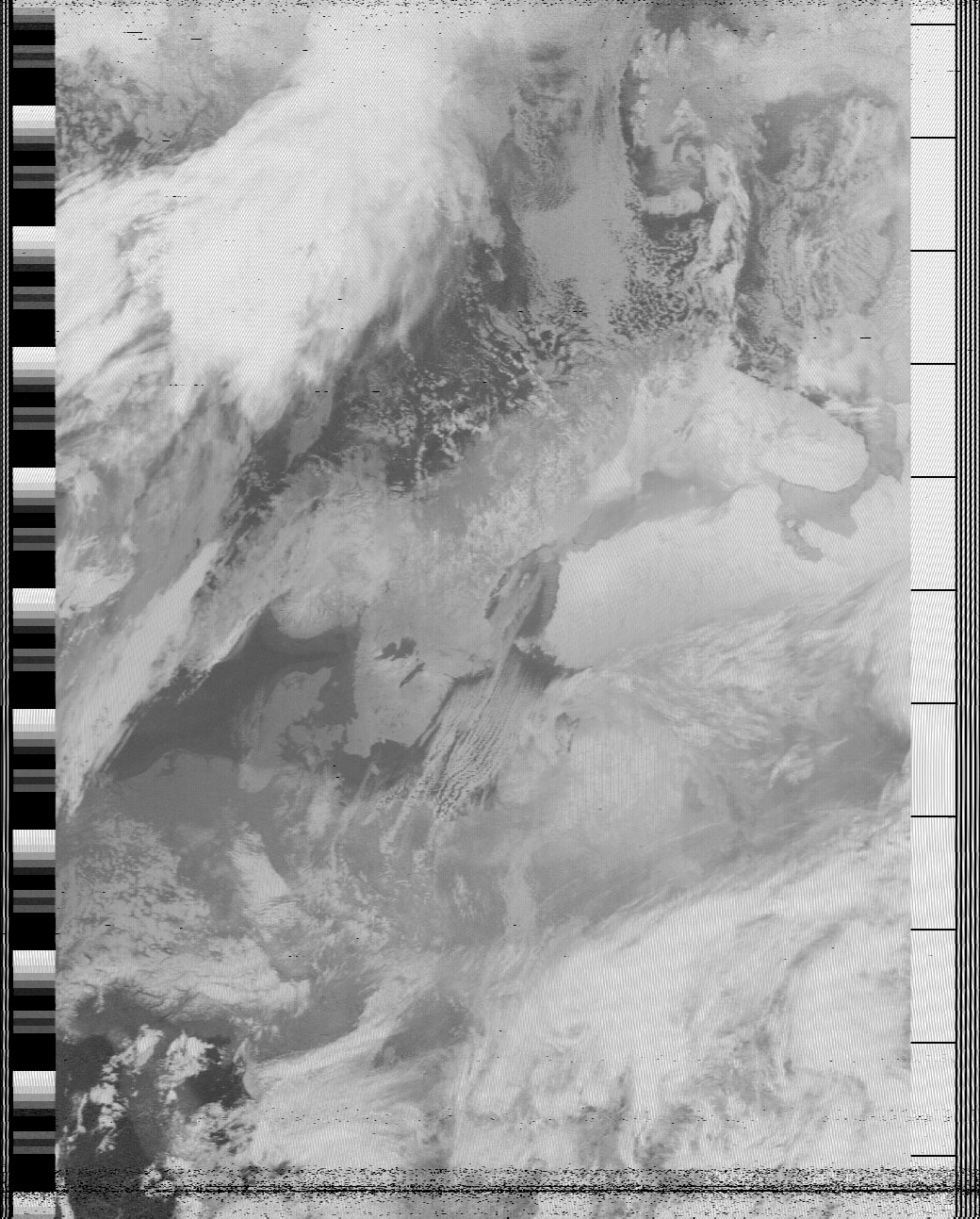 The first result(NOAA 15 on 990129 at 1545) |
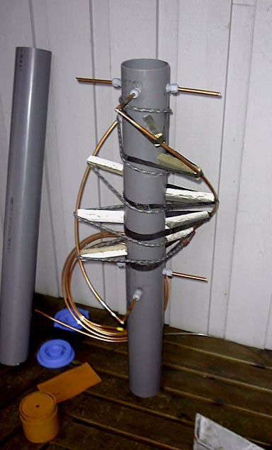 During construction. Note the temporary spacers to form the helices. At lower left the reinforcing disk and sleave for the lower end of the body curing inside a temporary holding sleave. Sleaves are made of split pipe. 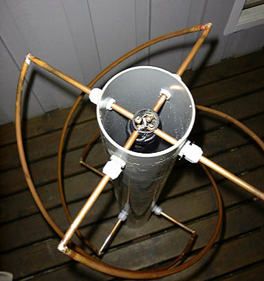
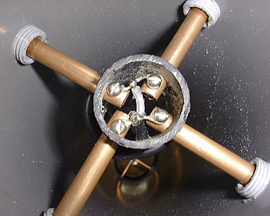 Balun and feed connection 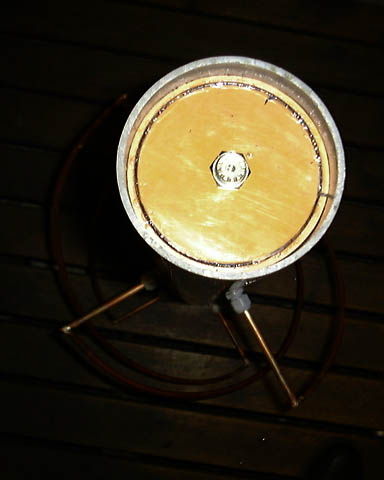 Female UHF connector in recessed bottom stiffening plate |
| X3DOM model here. and a small archive of images here. | |
|
Materials:
      120cm 110mm dia PVC tube - main body
      15cm   32mm dia PVC tube - balun and feed connection
      watertight end-cap for top
      PVC siffening disk and sleave for lower end of main body
      10cm 110 dia PVC tube for sleave around stiffening disk
      5m 8mm mini-bore copper tube
      20cm 5mm or less stiff wire
      short length of 1-1.5mm copper wire
      8 2.5x10mm stainless steel self-starting screws
      1 female UHF chassis connector
      8 8mm PG-glands (PG-9)
      150cm RG-58 coax cable for balun and local feed
      Silicon sealant
Dimensions: (mm)
                helical      bottom        top            height
                elements     elements      elements

   Long loop     2x812         1x374        2x181          560
   Short loop    2x758         1x356        2x172          512
Assembly: Drill and thread holes for PG-glands at 90° angles and same level at top of main body tube. Drill and thread holes 512 and 560mm below. Screw glands on place with silicon sealant. Cut all copper tubing for loops to size with 45° angles at ends in addtion to dimensions above. Mount both lower horizontal elements and corresponding top split elements on main body tube. Cut to size a series of spacers of wood (about 4) to secure helical elements while fixing. Insert stiffening wire at end of upper and lower elements, bend to 90° as joint reinforcement. Shape half-turn helical element and fix temporarily with spacers and bungee strap. Weld end joints. (Weld can be omitted for soldered 90° copper elbows if available.) Mount and weld one helical element in turn. Wrap horizontal part of loop entering the PG-gland with wet rag to absorb heat and prevent damage to gland while welding. Cut lower reinforcing disk to size and glue inside a guiding sleave of 10cm 110 PVC with slot along its entire length. Drill hole for UHF chassis connector and drill 2mm hole for self-starting screw to fix coax shield to chassis connector. Drill 4 8mm holes at 90° angles in one plane of 32mm pipe for balun and feed connector. Drill two 5mm holes in side of pipe 4 turns of coax above each other. Drill holes for self-starting screws in inner ends of upper elements of both half-turn helical loops. Form and solder loops at either end of 2 short lengths of copper wire for connector bridges. Thread coax inside 32mm balun pipe, out through lower 5mm hole, forming 4 turns of cable then in through upper 5mm hole. Strip and clean upper end and solder connector bridges to core and shield. Loosen glands and retract upper elements of loops to enter balun pipe. Screw connector bridges in place. Tighten glands making sure elements do not short. Connect lower end of feed to chassis connecter. Fix watertight top cover with 2 self-starting screws. Fix sleave and reinforcing disk in lower end with self-starting screw. 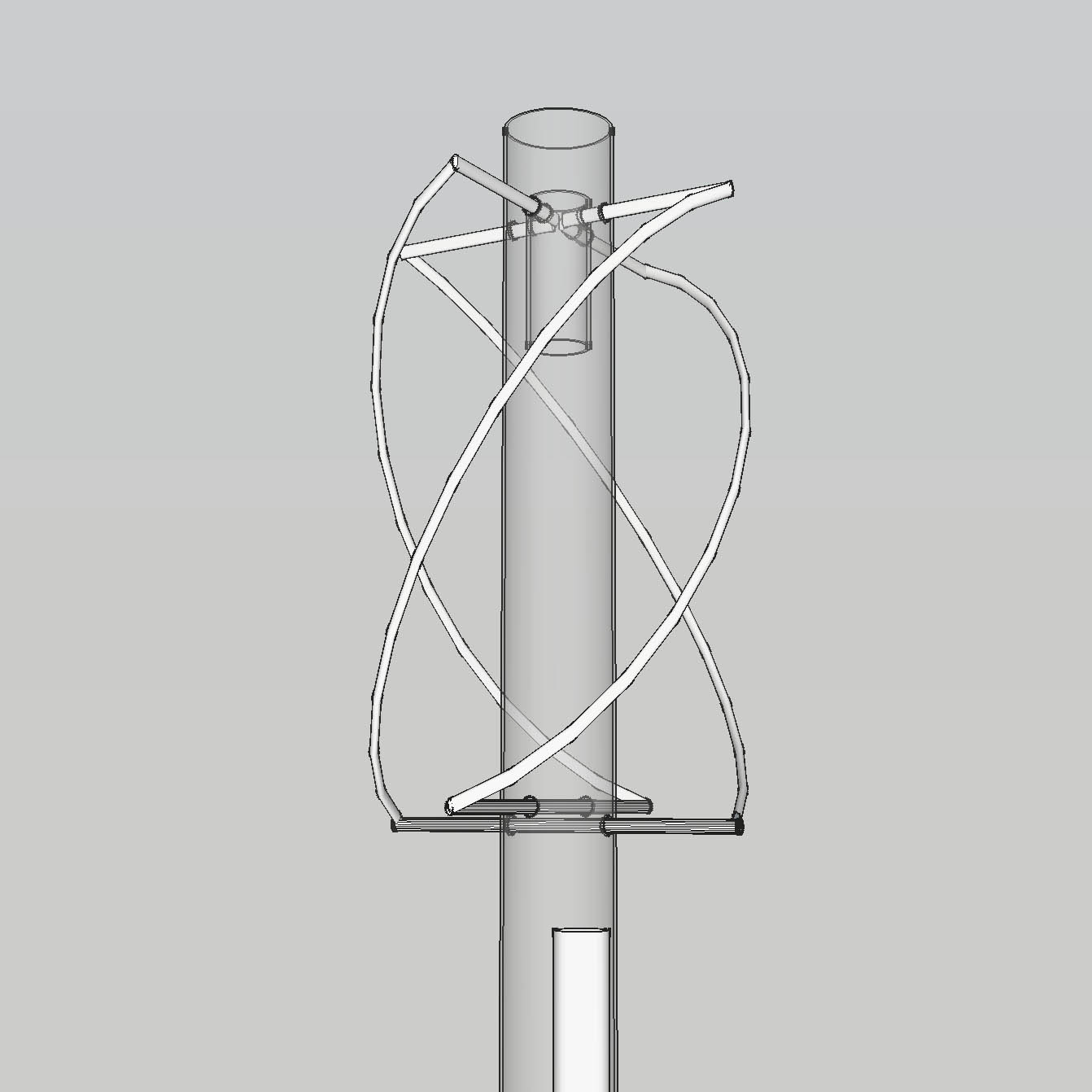 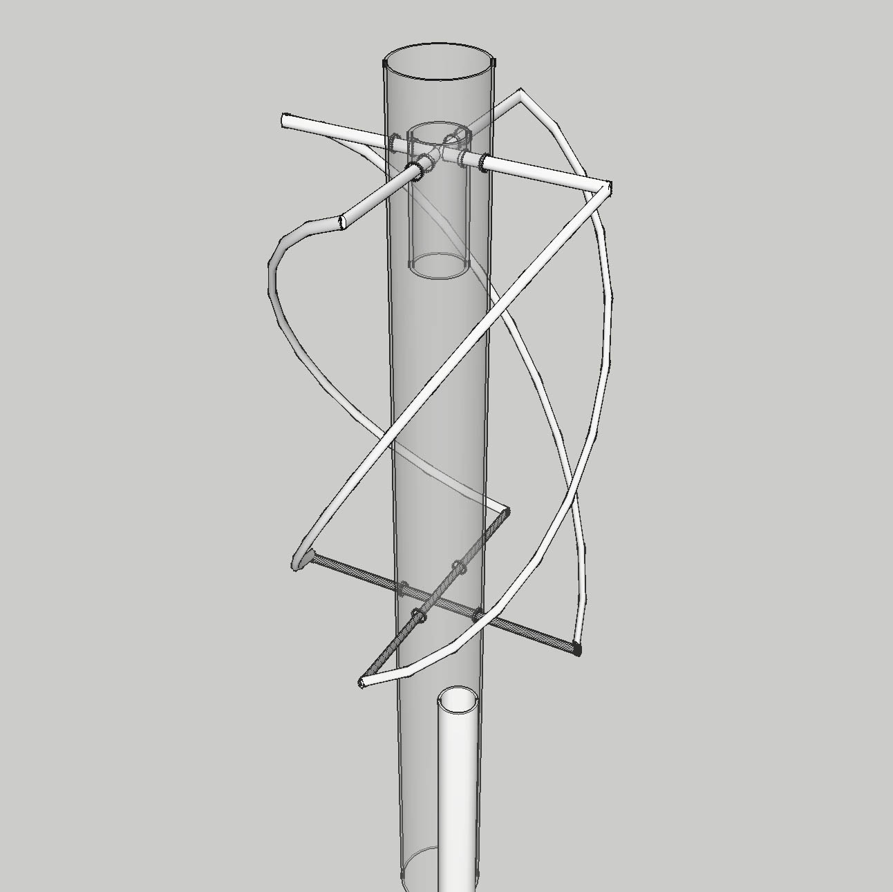 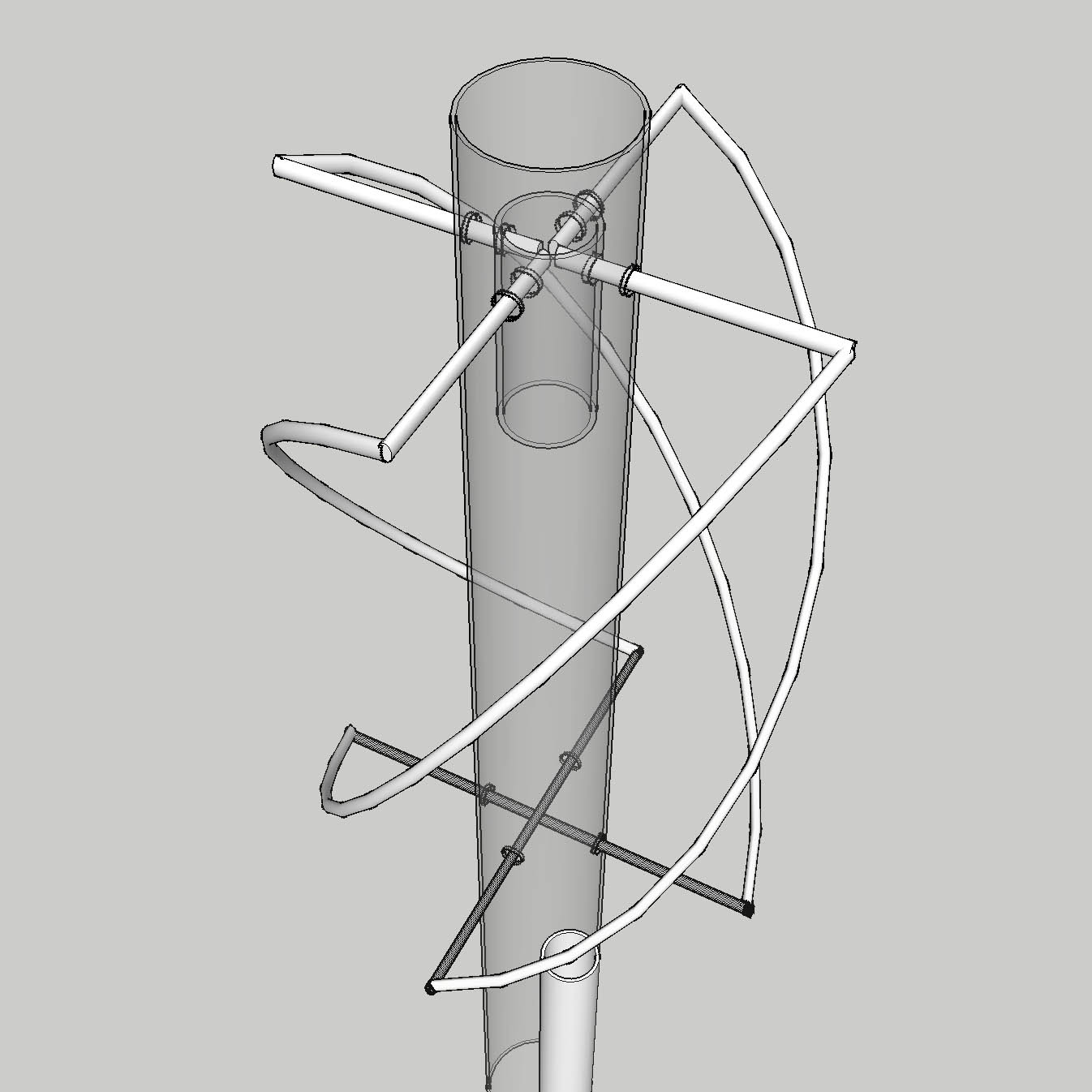 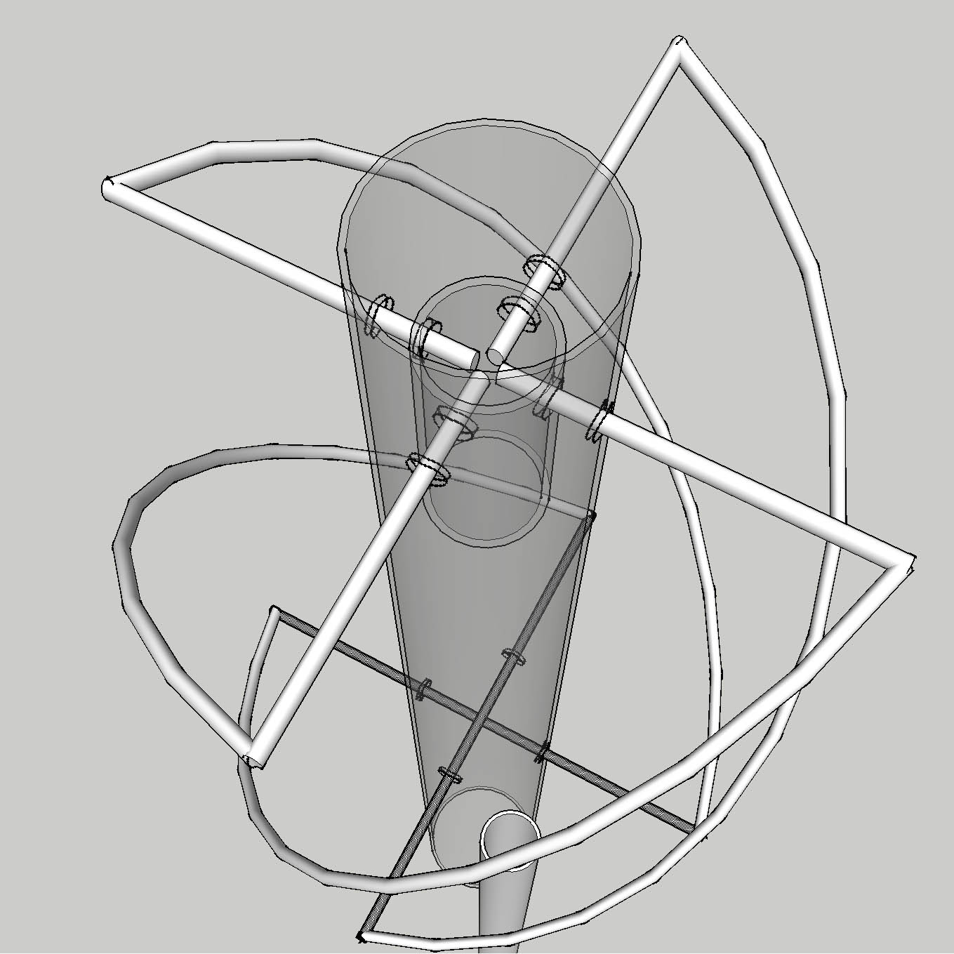 Screendumps from the 3D model Modifications: The main difference from Sykes & Cobey's model is the 110mm rather than 32mm pipe main body, the PG-glands and the simple copper wire connector bridges. The substantially larger diameter pipe and glands were adopted to provide a stiffer and more weather resistant construction for use in Norway, where build-up of snow and ice are a real hazard. The large main body would also provide a dry housing for a signal amplifier if needed. With the much stiffer construction the PCB disc end connector was replaced with the much simpler copper wire bridge. (Pictures during assembly here.) This version of the 135mHz quadrifilar antenna for APT reception is an adaptation from Bill Sykes and Bob Cobey's article Taming the QFH which appeared in the March 1997 RIG magazine. Thanks to John Makkinje (tapline@aol.com) who provided valuable advice and the Syke's and Cobey article. Børre Ludvigsen (borrel@hiof.no) - 990125 |
|
|
borrel@ludvigsen.hiof.no - pgp public key |
|